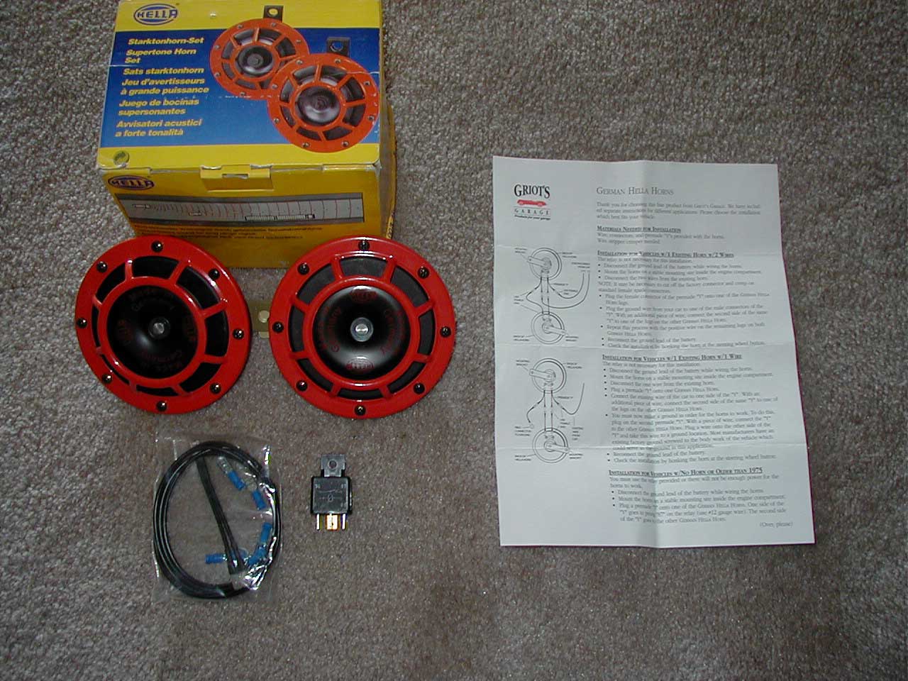
Photo 1: Hella Supertone Horn Set.
Blake "Dawgbert" Sobiloff
April 14, 2001
It's the weekend before taxes are due (in the U.S.), so what better way to procrastinate than to do a fun little upgrade to your motorcycle? In my case I decided it was time to upgrade the wimpy stock horn with something that has a little more authority.
Quite a while ago I had purchased a Hella Supertone Horn Set (3AG 003 399-801) from Griot's Garage, but had put off installing it because it was missing one of the two electrical "Y" cables it was supposed to come with. (Griot's offered to swap the entire horn set, but it seemed like more effort to send the set back than it would be to just wire my own "Y" cable.) Recently, some folks on the Sprint RS/ST mailing list had posted their satisfaction with the inexpensive horns from Fiamm, and this reminded me that I had my own horns waiting for me in a closet. "Quick, RATman, to the RAT cage!"
Rummaging through the closet for a moment, I found the horns buried towards the back. I opened the box and examined the contents (Photo 1).
|
|
|
Photo 1: Hella Supertone Horn Set.
|
The set includes two horns, one that has a 500 Hz tone and another that has a 300 Hz tone, and a wiring package. The package has two "Y" cables, about 18" of extra 14 A.W.G. cable, and a half-dozen male and female quick connect crimp spades. There's also a relay in case your particular application needs it. (The ST doesn't.) The horns are typical of German design: high quality materials (all steel) and slightly overbuilt. These puppies are heavy!
 |
|
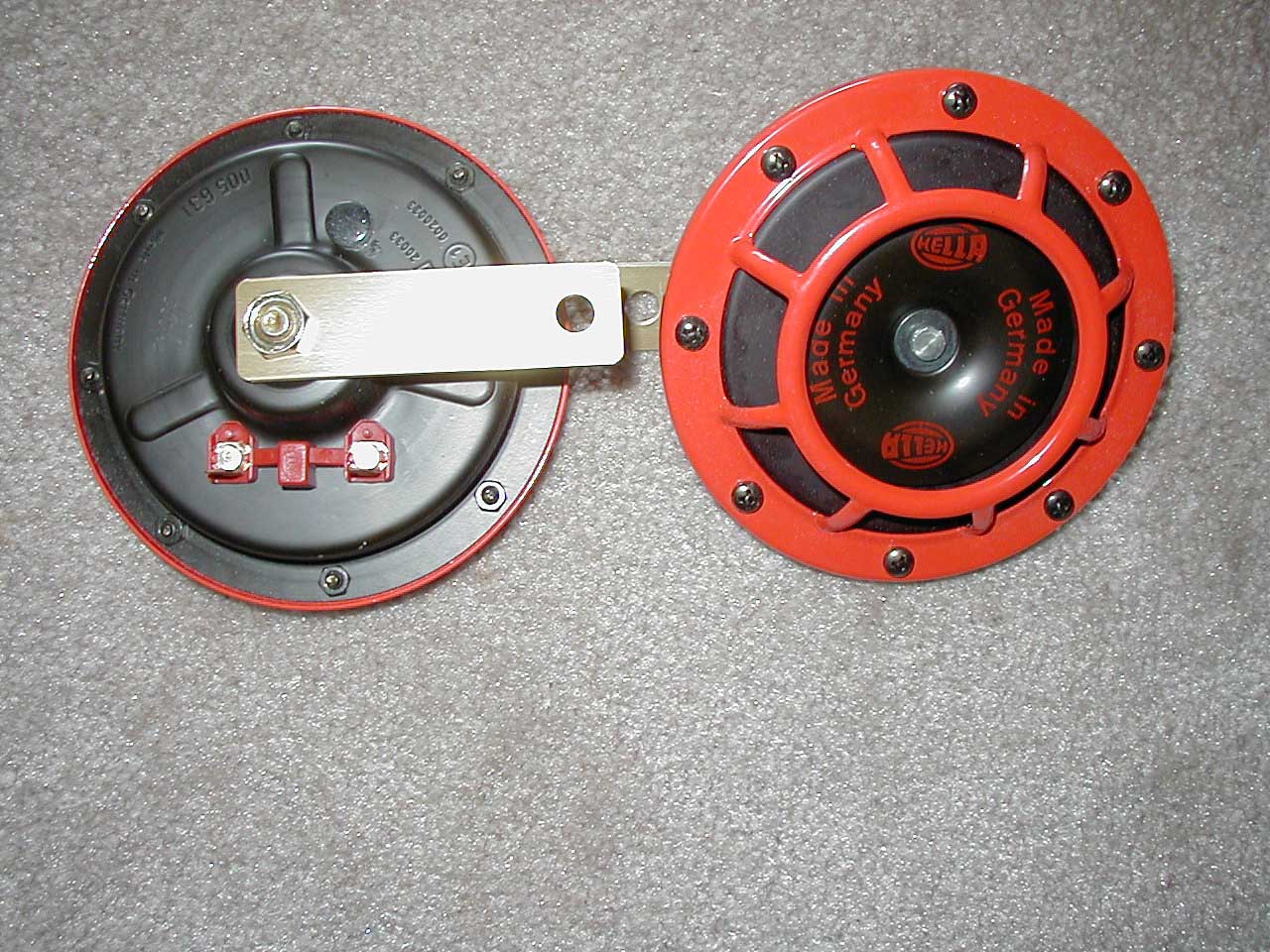
Photo 2: Hella horns up-close.
|
Griot's was nice enough to include a comprehensive set of instructions that tell you how to hook up these horns given your current horn wiring. The ST uses two wires for the stock horn, just like the Hella horns, making it fairly easy to wire them up (Photo 2). In a nutshell, one of the horns will have a "Y" cable attached to each spade on the back of the horn. One branch of each "Y" hooks up to the stock wires. The other branch of each "Y" connects to an extension cable that runs to the second horn. Polarity doesn't seem to matter.
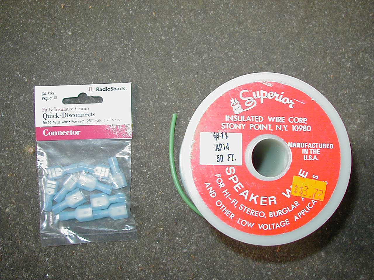
Since my set was missing one of the "Y" cables, I needed to run out to Radio Shack and get some extra connectors. I decided on the "Fully Insulated Crimp Quick-Disconnects" for 14-16 gauge wire (64-3133). The connectors that came with the Hella kit were uninsulated; that might be fine in an automotive application, but motorcycle electronics tend to be more exposed to the elements. I already had some old wire lying around (Photo 3).
 |
|
Photo 3: Extra electrical parts.
|
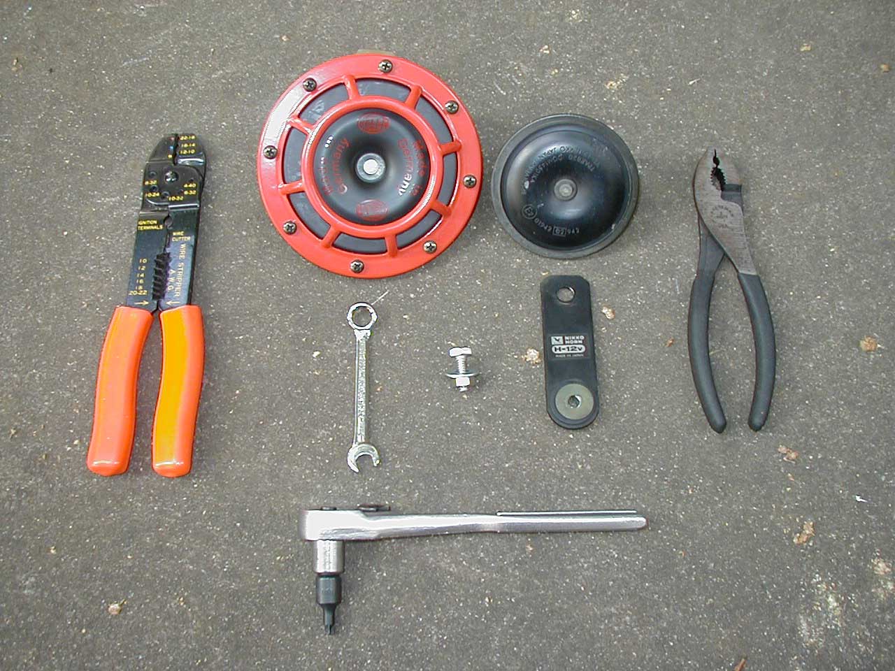
Next I got all my tools ready. OK, I just lied. I got all the tools ready that I thought I'd need, but then I ended up making several trips from the garage to the apartment to get more. (You folks with private garages are lucky!) Here's what I ended up using — see Photo 4 for most, but not all, of the tools:
 |
|
|
Photo 4: Most of the tools needed.
|
List 1: All the tools and parts I ended up using.
|
Photo 4 also lets you compare the stock horn to one of the Hella horns — quite the size difference!
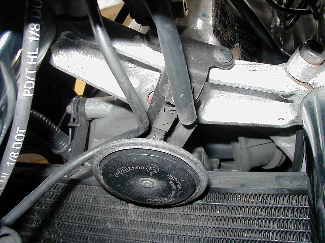
With the bike up on its center stand, I took a look at the stock horn. It's that tiny little disk hiding behind the front forks (Photo 5).
 |
|
Photo 5: The stock horn.
|
It's attached to an arm that screws onto an L-shaped bracket connected to the lower triple T by two Torx screws. I removed the horn and bracket, then disconnected the electrical leads from the horn. It took about two seconds to figure out that there was no way to fit both of the new horns in the same location. So, off came the left hand side panel. Looking underneath the instrument cluster, the best place to hang it looked to be from part of the instrument cluster's support frame.
 |
|
Photo 6: Left hand side mounting point.
|
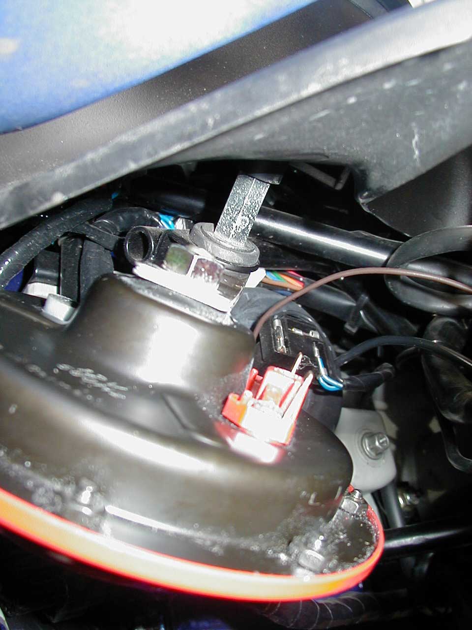
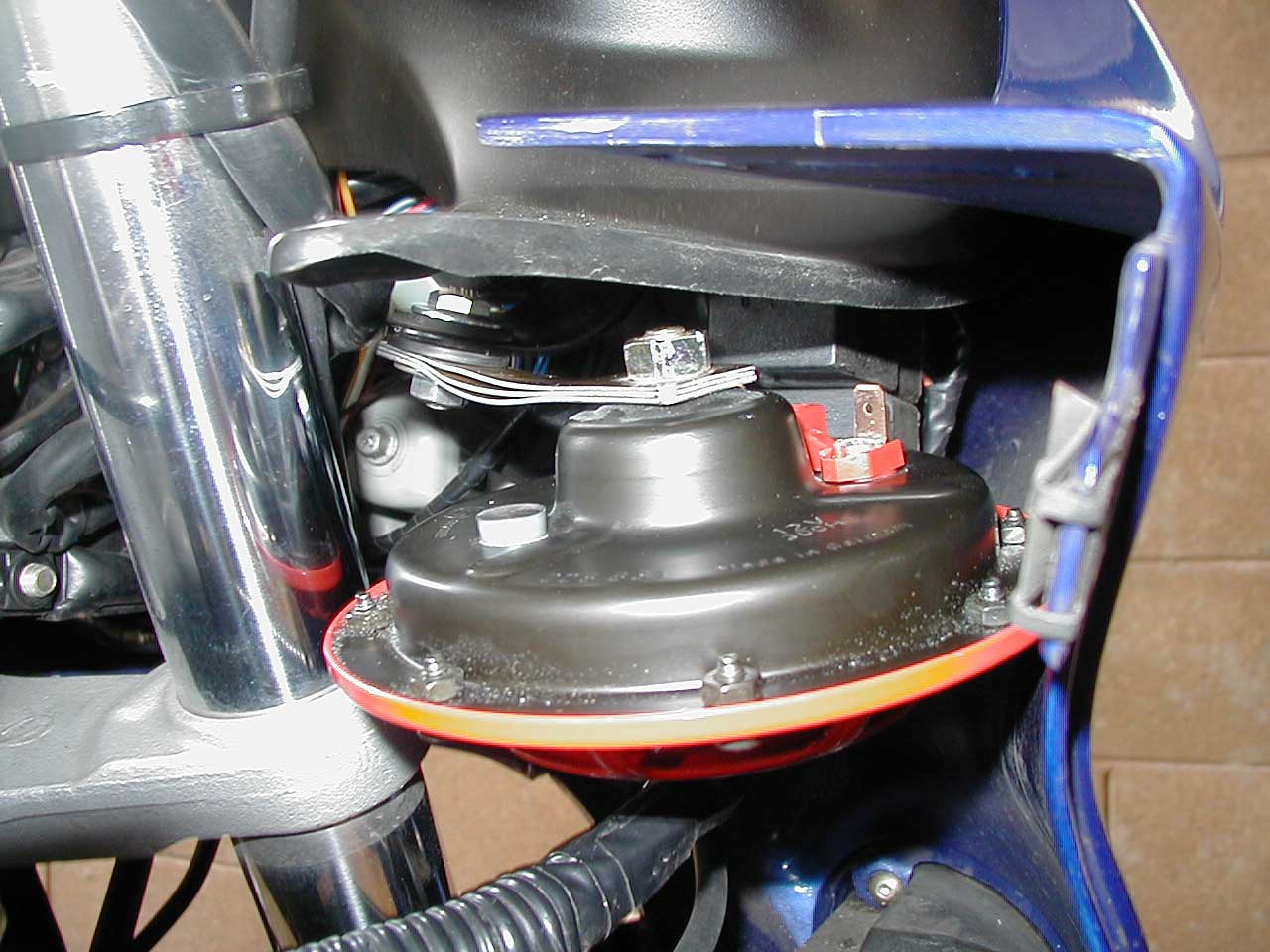
There's a 10mm nut at the bottom of one of the vertical posts, and there's enough extra thread on the post to accept the Hella horn's mounting bracket. Photo 6 shows the mounting point with the horn already installed. Note that you'll have to bend the end of the bracket about 1/2" (towards the back of horn) to get the horn to snuggle up against the underside of the cockpit valence. If you don't position the horn correctly it'll get hit by the left fork as it turns. I'd also recommend not letting the horn rest against the bodywork directly since it might buzz or vibrate if it comes into contact with the plastic. Fortunately, it's pretty easy to bend the Hella horn's bracket. See Photo 7 for a little more perspective on how the horn is positioned.
 |
|
Photo 7: Left hand side horn installed.
|
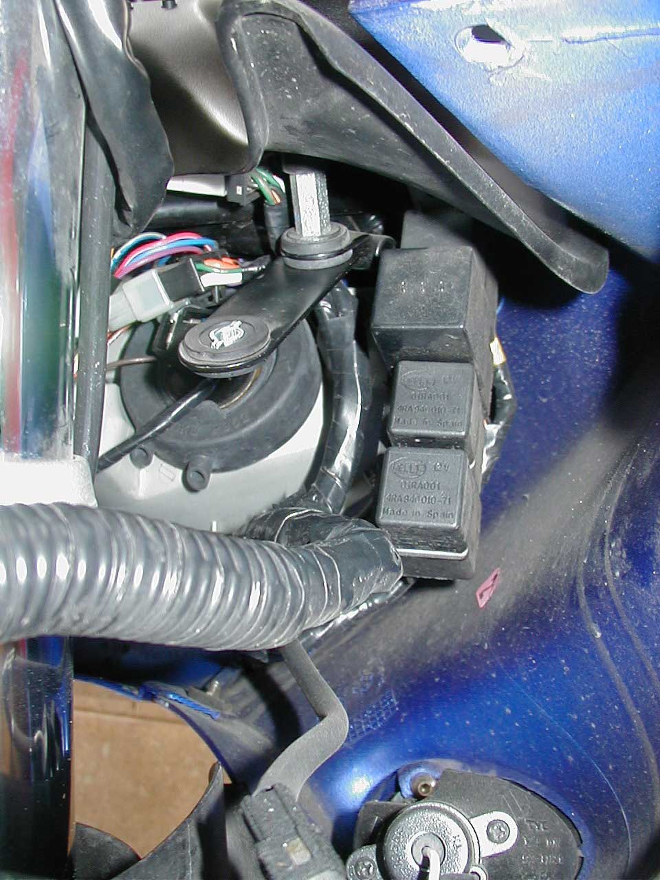
Cool, that was fairly easy. Let's do the right hand side. Off with the right hand side fairing and... what's this? (Photo 8)
 |
|
Photo 8: Right hand side relays and old horn
bracket.
|
Argh! There are some relays here that take up the space where the horn needs to fit. After trying a couple of different ideas, I discovered that I could use the arm from the old horn's mounting hardware to move the new horn back far enough to clear the relays. Photo 8 shows this arm already connected to the mounting point. Note that the old horn's arm has a rubber damper on one end, making it too thick to mount to the mount point. Connect the plain end to the mount point instead. Also, rotate the arm so that it's forward of the right fork. This will keep it from hitting the fork as it swings back and forth, but there is less clearance than on the left hand side.
 |
|
Photo 9: Right hand side horn installed.
|
Photo 9 shows the right hand side horn connected to the old horn's arm; this is where that extra nut, bolt, and washer come in. You can't see it too well in the photo, but you'll have to bend both the old horn's arm and the new horn's bracket to get the horn to rest at the right angle. Again, double check to make sure that the fork doesn't hit the horn or brackets at any point it its movement side to side.
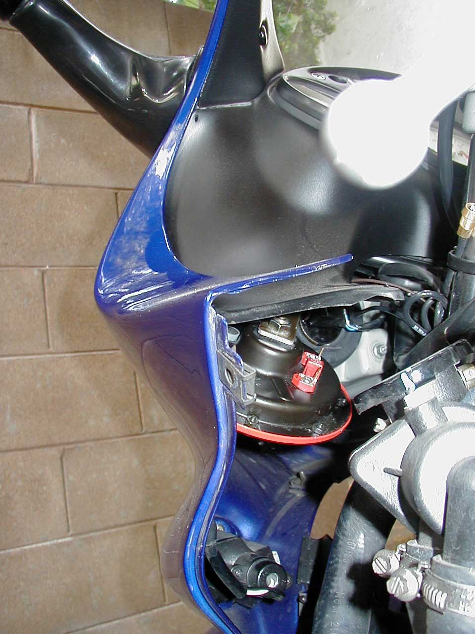
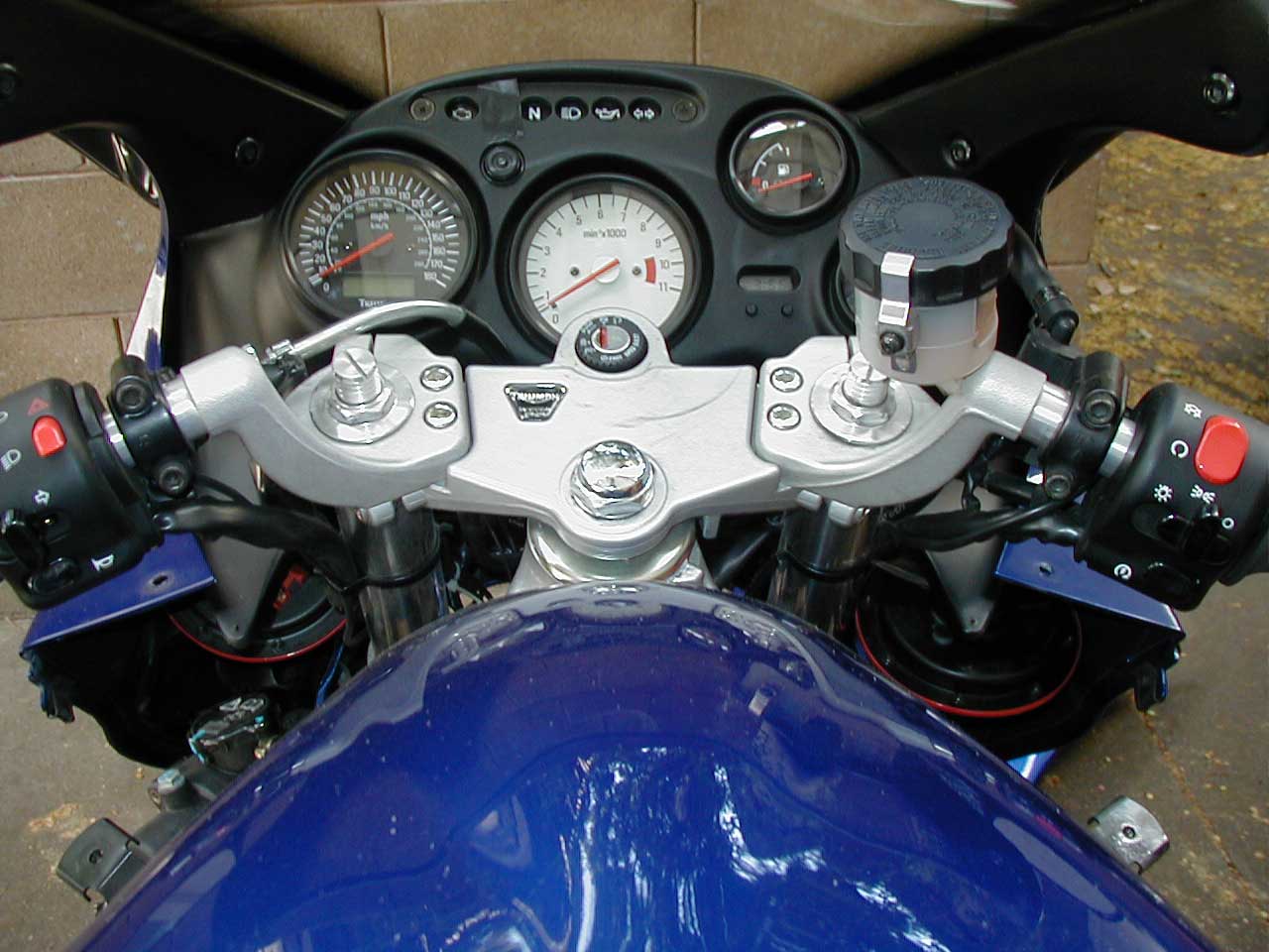
At this point, step back and admire your work (Photo 10).
 |
|
Photo 10: The view from the driver's seat.
|
From here it's just a matter of making the electrical connections. Route the wires that go from one horn to the other through the instrument cluster's support frame to keep them out of the front forks. (What, again with the front forks?) Once everything's hooked up, turn the ignition on and sniff for smoke. Assuming that your work passes the smoke test, hit the horn button. Music! If not, try just connecting one horn or the other to help isolate where the wiring problem is.
Button everything back up and go grab an adult beverage to celebrate. You've just improved your bike's visibility to other vehicles on the road and made your ride a little more unique.